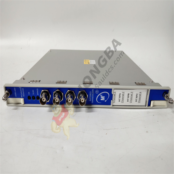
Brand: Bently Nevada
P/ n:3500/40M
Description: Proximitor displacement monitor
Origin: United States
Xiamen Xiongba Electronic Commerce Co., LTD. (Zhangzhou Branch)
Unit 2009, Creative Center, 1733 Luling Road, Siming District, Xiamen, China
M: + 86 18059884797
Email :sales@xiongbagk.cn
Website:www.sauldcs.com/www.xiongbagk.cn

3500/40M
The 3500/40M Proximitor is a 4-channel displacement monitor that receives input from the Bentley Nevada displacement sensor, on the signal
After processing, various vibration and displacement measurements are generated,
and the processed signals are combined with user-programmable alarm setting points Comparison.
You can use 3500 framework configuration software to configure each channel of 3500/40m, so that it has the following functions:
• Radial vibration
• Axial displacement
• differential expansion Eccentric shaft,
• REBAM a.
Rolling bearing vibration R
Note: The monitor channel is configured in pairs and can perform 2 of the above functions at a time. Go to 1 for channels 1 and 2
Channel 3 and channel 4 perform another function or the same function. The main functions of the 3500/40M monitor are:
1) By continuously comparing the current value of machine vibration with the alarm value in the configuration,
and driving the alarm system, thus Achieve the purpose of protecting the machine;
2) Provide vibration information of key equipment for operators and maintenance personnel.
By configuration, each channel typically processes the input signal into a “static value.” Each static value has a well-configured warning
Alarm value, every two static values can be configured with a danger alarm value. The delay time of alarm can be set by software.
Front panel LED (light emitting diode) OK LED: indicates 3500/40M normal operation
TX/RX LED: indicates that 3500/40M is communicating with other modules in the 3500 frame
Bypass LED: indicates that 3500/40M is in bypass mode
Sensor buffer output: the front board pair shall have coaxial connectors for each channel and each coaxial connector Short circuit protection
1. Front view of the main module
2. State LED
3. Buffer sensor output
4. I/O module
5. Safety grid I/O module, Inside the terminal
6.internal terminal
7. I/O module, external terminal We can also judge the failure status of the module according to the status of each LED (light-emitting diode) on the front panel,
The other modules are similar.
 中文版
中文版


