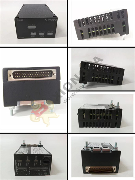
The GE RST analog terminal board DS200TBQCG1B has two wiring terminals. Each block contains 83 signal line terminals. The GE RST analog terminal board DS200TBQCG1B also contains 15 jumpers, three 40-pin connectors, and three 34-pin connectors. Because there are multiple 40 – and 34-pin connectors, the guidelines for connecting and disconnecting ribbon cables must be followed. The DS200TBQCG1B uses the abbreviation TBQC in many GE manuals and data sheets, which can also be called milliamps input/Output Terminal Board.

DS200TBQCG1B
The 40-pin and 34-pin connectors are assigned ids on the board. Write the connector ID on a piece of tape and press it against the ribbon cable. This makes it easier to connect the cables on the replacement plate.
DS200TBQCG1B is connected as follows:
JBR – Writes and reads I/O signals from TCQA respectively
JFR – Writes LVDT/R input communications to TCQA
JBS/T, JFS/T, and TEST – not usually used.
This information can be found in Table GEH-6153 on the GE website
 中文版
中文版


