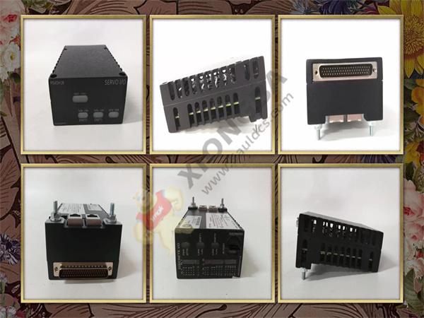
GE Gas Turbine terminal board DS200TBQGG1A has 2 terminals. Each block contains 95 signal line terminals. The GE Gas Turbine terminal board DS200TBQGG1A also contains 2 jumpers and 6 34-pin connectors. The board is 11.25 inches wide and 3 inches high and contains five holes for attaching the board to the inside of the drive. The drive cabinet contains a rack for the support plate and has screw holes aligned with the holes in the plate.

DS200TBQGG1A
When you are ready to install the replacement plate, check the cabinet and pay attention to the installation position of the old plate. The best practice is to install the replacement in the same location. It is also important to note where the cable is connected on the circuit board and how the cable is routed. This also applies to signal wires connected to terminals. Improper cable wiring can inhibit or block the free flow of air in the driver. The components in the drive generate heat, and the drive uses air currents to keep the inside of the drive cool. Another benefit of cabling if the room gets too hot is that the power cord can interfere with the signal cable if the two types of cables come too close together. Interference may also occur if the signal and power cables are routed parallel. Proper cabling will prevent interference.
 中文版
中文版


