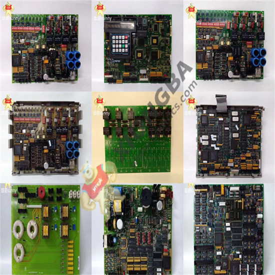
GE I/O TC2000 analog board DS200TCCBG3BED has an 80196 microprocessor and multiple PROM modules. It also contains an LED and 2 50-pin connectors. The LED is visible from the side view of the board. The ID of the 50-pin connector is JCC and JDD. There are also five 34-pin connectors on the board. Since multiple ribbon cables may be connected to the board, there are guidelines to follow. Before disconnecting the ribbon cables, note how they are routed inside the drive cabinet. Cabling is important because routing signal cables near power cables can interfere with the signal. The best practice is to lay the signal cables far away from the power cables and minimize the length of the two cables in parallel. Interference is minimized if the power and signal cables are crossed at a 90 degree Angle. If the board contains fiber optic cables, you should know that they are not interfered with and can be located close to the power cord.

DS200TCCBG3BED
 中文版
中文版


