Jumper cables, one for the input module (DI or AI) and one for the output module (DO).
TC-306-02: for input modules (DI: T8402 and T8403 or AI: T8431 and T8433)
TC-308-02: for output modules (DO: T8451, T8461 or T8471)
1) Identify the slot containing the failed module that needs to be replaced. identify and record
Module type and model.
2) Identify the SmartSlot to accommodate the replacement module.
– If a smart slot already contains an active module, the slot will be used as
Replacing a previously failed I/O module without being able to replace another
unit
-If the SmartSlot contains a module in standby, remove the standby module.
– Smart slots must be empty before proceeding.
3) Open the cabinet door and swing frame. Connect one end of the appropriate SmartSlot
The cable that connects to the rear of the I/O cable cover on the rear of the chassis where the failed module resides
Installed. Connect the other end to an empty SmartSlot location on the chassis.
Secure the cables with the screws provided.
4) Install the same spare replacement module in the SmartSlot. If the original module
In case of failure, the standby module will automatically enter the standby state and receive education. once
After the educational process is completed, the new modules will be automatically activated
Assume control.
5) Once the original module is in standby and the backup module is active, fault the original module
The module can be removed using the eject key and release lever.
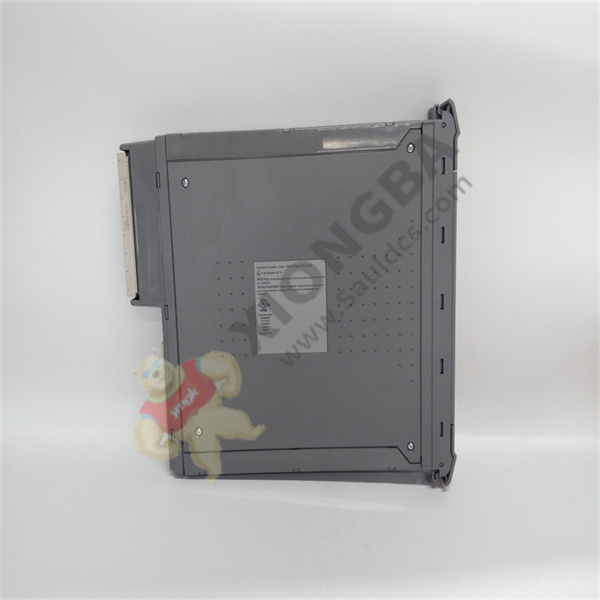
T8461 Mounts on DIN rail Associated output module I/O connectors
 中文版
中文版


