1.1 Working Principle
Instrument measurement adopts the principle of approaching eddy current. The probe is composed of a coil with a high frequency signal. When the metal surface of the measured shaft changes relative position with the probe, the size of the eddy current formed changes, so that the energy loss of the high frequency signal in the probe changes. The change signal is converted into a voltage signal corresponding to the voltage of the gap measured by the probe through the preprocessor, and the signal enters the monitor in the component box. Display as a reading after conversion inside the monitor.
1.2 Structure of the Bentley 3300 system loop
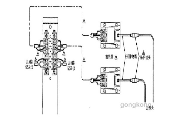
The system consists of a 3300 series instrument assembly box with a corresponding preamplifier and a sensor (probe) with cable. Each parameter is measured by a special probe preprocessor and a monitor.
Composition of Bentley 3300 displacement and vibration detection system:
2 Sensor Verification
The main calibration instruments include Bentley TK3-2E calibrator, 4-digit semi-digital voltmeter, 24V DC regulated power supply and function generator.
2.1 Verification of sensors
1. Connect the probe with the extension cable, extend the other end of the cable to the preprocessor, the power end of the preprocessor (-24VDC), the common end (com), access the -24VDC power supply, the public end and the output end to the digital voltmeter.
2. Fix the probe on the probe seat with an appropriate probe clamp, so that the top part of the probe contacts the calibration target.
3. Send -24VDC to the power terminal and the common terminal of the preprocessor, then adjust the screw micrometer on the TK3-2E calibrator so that the indicator value is at 0mm, then increase the indicator value of the micrometer to 0.25mm, and record the voltage value of the digital voltmeter (this value is the output voltage of the preprocessor). Increase the gap at 0.25mm each time until the indicated value is 2.5mm, and record the output voltage value each time (check point no less than 10 points).
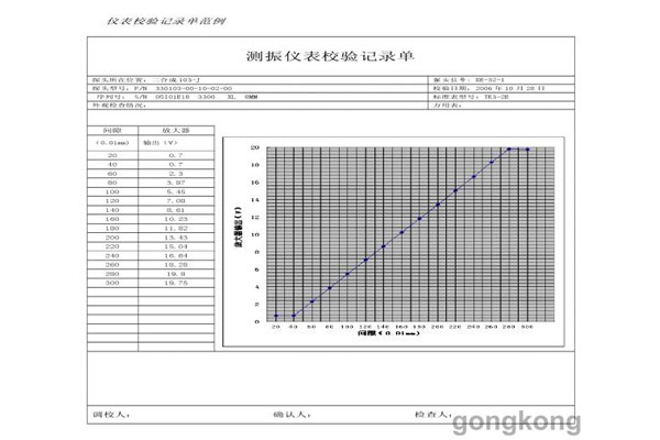
According to the recorded data, according to the form of the calibration curve of the axial displacement sensor, the gap voltage curve of the calibrated probe sensor system is drawn, which reflects the characteristics of the sensor.
According to the drawn gap – voltage curve, determine the linear range of the sensor system, should not be less than 2mm. The sensitivity of the sensor system is calculated to be 7.874V/mm, and the nonlinear deviation in the linear range is no more than 20um. Voltage increment divided by gap increment is sensitivity. The linear center of the sensor is the static set point of the axial displacement sensor.
The calibration method of the vibration sensor is the same as that of the data recording coaxial displacement sensor. The gap voltage curve should also be drawn to calculate the sensitivity of the sensor system. The error of the sensor system is not more than ±5% within the linear range of 2mm. The linear center of the sensor is the installation reference point of the shaft vibration sensor.
The calibration record sheet of shaft vibration instrument is shown as follows:
3. Summary
In our factory, vibration and displacement measuring instruments of unit shafting are all BENTLY 3300 system sensors. Therefore, as instrument maintenance personnel, we must master the calibration work of 3300 series sensors skillfully. This paper mainly introduces the calibration process of 3300 series sensor, hoping to play a certain reference role for peers.
 中文版
中文版


