中文版
中文版

Description
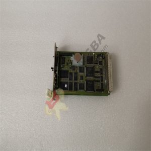
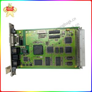
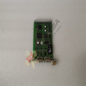
F8621A F 8650X Central module
Product description
For the serial interface only the bus station no. 1-31 can be set.
Within an Ethernet network the bus station no. can be set from 1 to 99. Therefore the switches S1-6/7 must be set in addition to the switches S1-1/2/3/4/5.
The number of the communication partners within a network is still limited to 64.
This enhanced setting of the bus station no. is only possible from operating system BS41q/51q V7.0-8 (05.31) of the central module.
Applications with the communication module F 8627X:
– connection of the central module to a PADT (ELOP II TCP)
– connection to other communication partners within an Ethernet network (safeethernet, Modbus TCP)
The communication runs from the central module via the backplane bus to the communication module F 8627X and from the Ethernet ports of the F 8627X into the Ethernet network and vice versa.
Special features of the central module:
– Self-education: from operating system BS41q/51q V7.0-8 (05.31)
– ELOP II TCP: from operating system BS41q/51q V7.0-8 (05.31)
Further informations about the bus station no., ELOP II TCP, loading of operating systems and application programs (self-education) et al. corresponding to the central module you will find in the data sheet of the F8627X as well as the operating system manual of H41q/H51q and the safety manual of H41q/H51q.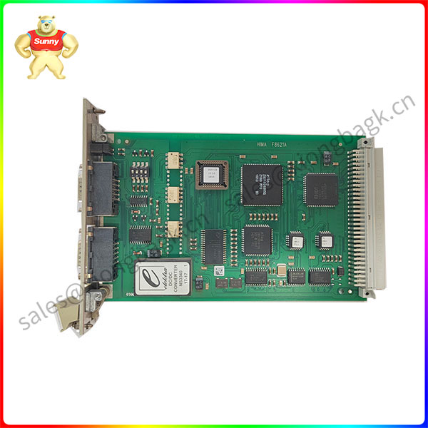
Product parameter
Microprocessors INTEL 386EX, 32 bits
Clock frequency 25 MHz
Memory per microprocessor
Operating System Flash-EPROM 1 MB
User program Flash-EPROM 1 MB *
Data SRAM 1 MB *
* Degree of utilization depending on operating system version
Interfaces Two serial interfaces RS 485 with electric isolation
Diagnostic display Four digit matrix display with selectable information
Shutdown on fault Safety-related watchdog with output 24 V,
loadable up to 500 mA, short-circuit proof
Construction Two European standard PCBs,
one PCB for the diagnostic display
Space requirement 8 SU
Operating data 5 V / 2 A
Application field
Diagnostic display of the central module
– Four digit alphanumerical display,
– two LEDs for the general display of errors (CPU for the central modules, IO for the testable input/output modules),
– two toggle switches to request detailed error information,
– push-button ACK resets the error indication; in failure stop ACK behaves like restarting the system.
For further information on the diagnostic display and lists of error codes, refer to the documentation “Functions of the operational system BS 41q/51q” (also on ELOP II CD).
Notes for start-up and maintenance
– Lifetime of the buffer battery (without voltage feeding): 1000 days at TA = 25 °C 200 days at TA = 60 °C
– It is recommended to change the buffer battery (CPU in operation) at the latest after 6 years, or with display BATI within three months (Lithium battery, e.g. type CR 2477N, HIMA part no. 44 0000018)
– Check the bus station no. and transmission rate at switch S1 for correct settings
– Important: When upgrading an F 8650 to an F 8650X module the fan concept has also to be changed!
Please contact Sunny sales@xiongbagk.cn for the best price.
➱ sales manager: Sunny
➱ email mailto: sales@xiongbagk.cn
➱ Skype/WeChat: 18059884797
➱ phone/Whatsapp: + 86 18059884797
➱ QQ: 3095989363
➱ Website:www.sauldcs.com