中文版
中文版

Description
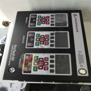
UG10 8526-653 UG-10 Dial or Lever Governors
Product Description
Mounting base dimensions for the UG-5.7, UG-8, or UG-10 Dial or Lever Governors are identical. See Figure 1 for mounting base dimensions. Place a gasket between the base of the governor and the engine mounting pad. Mount the governor squarely on its mounting pad and in line with the drive. Torque the mounting bolts evenly. There must be no movement or rocking of the actuator on the engine mounting pad.
Use the correct coupling between the governor and the prime mover drive. Be sure there is no binding, excessive side loading of the governor drive shaft, or looseness in the coupling. There must be no force pushing the governor drive shaft into the governor.
A misaligned drive shaft could break and could cause an overspeed condition or runaway engine.
If the engine drive pad is at an angle (from 0 degrees to 45 degrees maximum), the governor must be installed with the front panel in the upper position.
If an optional keyed drive is used when installing the governor, avoid rough gear teeth and incorrect backlash. Refer to the prime-mover manufacturer’s specifications for the correct amount of backlash and adjustment procedure.
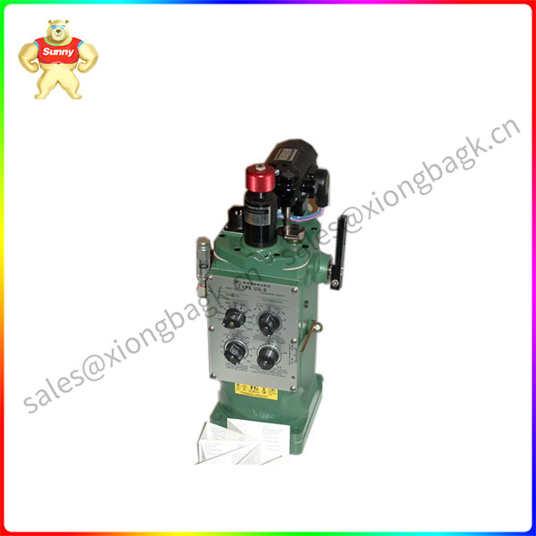
UG-8L
Product parameter
The recommended continuous operating temperature of the oil is 60 to 93 °C (140 to 200 °F). The ambient temperature limits are –29 to +93 °C (–20 to +200 °F.
Use Tables 1 and 2 as a guide in the selection of a suitable lubricating hydraulic oil.
Measure the temperature of the governor on the outside lower part of the case.
The actual oil temperature will be slightly warmer by approximately 6 Celsius degrees (10 Fahrenheit degrees).
Fill the governor with the selected oil to the mark on the oil sight glass. Oil must be visible in the glass under all operating conditions.
Application field
Start the engine as instructed by the engine manufacturer. For a safe start-up, adjust the speed setting knob on the governor for a reduced speed and allow the engine to warm up.
Once the governor has reached its operating temperature, make the following compensation adjustments without load on the prime mover:
- Bleed trapped air from the governor oil passages using the following procedure:
Loosen the nut holding the compensation adjusting pointer and set the pointer as far as it will go towards maximum compensation. Tighten the nut.
Open the needle valve two turns ccw.
Allow the prime mover to hunt for approximately 30 seconds to bleed trapped air.
- Loosen the nut holding the compensation pointer and set the pointer as far as it will go towards minimum compensation. Tighten the nut again.
- Gradually close the needle valve until hunting stops. If hunting does not stop, open the needle valve three to five turns from the closed position, and move the compensation pointer up by two marks on the front panel indicator scale. Again, gradually close the needle valve until hunting stops. If hunting does not stop, repeat this procedure.
- Check governor stability by manually disturbing the governor speed setting.
The compensation adjustment is satisfactory when the governor returns to speed with only a slight overshoot or undershoot.
- The needle valve must not be closed completely, normal position is from 1/2 to 3/4 turn open. Closing the needle valve more than necessary makes the governor slow to return to normal speed after a load change. It is also desirable to have as little compensation as possible. Once the needle valve adjustment is correct, it is not necessary to change the setting except for large changes in temperature which affect governor oil viscosity.
- When the compensation adjustment is correct, tighten the compensation pointer, and install the needle valve access plug and seal washer.
Other related product recommendations:
| MVI56-ADM Prosoft Programmable Application Development Module |
| BMXCPS2010 Schneider Standard power module |
| BMXDDO6402K Schneider discrete DC output module |
| BMXDDI3202K Schneider discrete input module |
| PCI-6221 779066-01 Multifunction I/O Device |
| SHC68-68-EPM NI Multifunctional cable |
| 05701-A-0361 Backplane Serial communication controllers and monitors |
| AI03 ABB AI module 2-3-4 Wire RTDs |
| AI02J ABB AI module 2-3-4 Wire RTDs |
| IOC-555-D 17-550555-001 GE Electronic components |
| PC834-001-T PACIFIC SCIENTIFIC Brushless Servo Drive |
| 8440-1666 B SPM-D11/LSXR features 12/24 VDC power supply |
| IC670ALG310 GE voltage-source analog output module |
| PM866K01 3BSE050198R1 AC800M processor unit |
| 81001-340-71-R Allen Bradley Inverter processing module |
| PXI-8423 NI PXI-8423/2 RS-485 Interface |
| AD02 ABB AI module 2-3-4 Wire RTDs |
| MVME55006E-0163 MOTOROLA VMEbus Single-Board Computer |
| 531X301DCCAFG2 GE DRIVE CONTROL BOARD |
| A6370D Emerson A6370 Overspeed Protection Monitor |
| 1715-TASOB8DE Allen Bradley termination assembly |
| 4PP065.0571-X74F Power Panel PP65 |
| 2094-BC02-M02 Kinetix 6000 Integrated Axis Module (IAM) |
| MVI56E-MCM ControlLogix series communication module |
| 1769-L32E CompactLogix Modular controller |
| DI810 16 Digital Input module |
Please contact Sunny sales@xiongbagk.cn for the best price.
➱ sales manager: Sunny
➱ email mailto: sales@xiongbagk.cn
➱ Skype/WeChat: 18059884797
➱ phone/Whatsapp: + 86 18059884797
➱ QQ: 3095989363
➱ Website:www.sauldcs.com