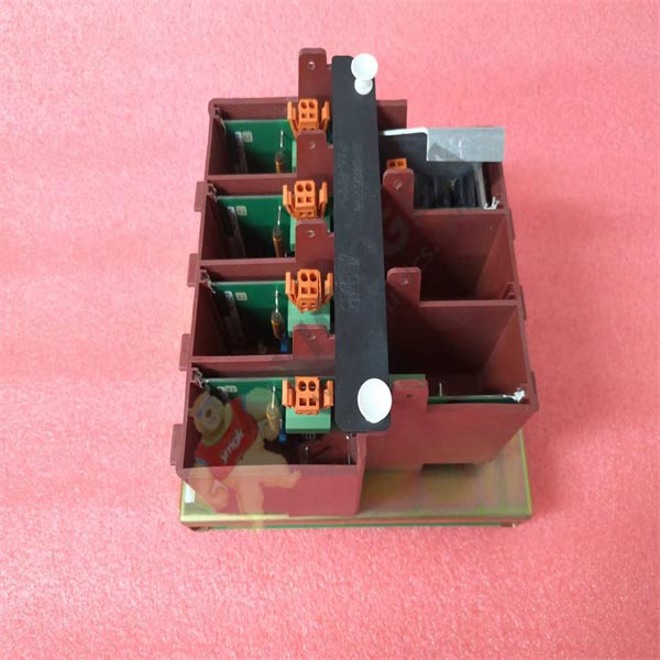
KUC755AE106 3BHB005243R0106 ABB

KUC755AE106
When KUC755AE106 3BHB005243R0106 synchronous motor starts, the frequency of rotor induced voltage gradually decreases with the rise of speed. Once the synchronous motor starts, the single chip microcomputer will immediately detect the rotor induced half cycle time, starting from 20ms, the digital tube is marked “9”, and every 20ms increase in the middle, Digital minus 1, to 200ms digital tube display “0”. In the asynchronous starting process of KUC755AE106 3BHB005243R0106 synchronous motor, when the rotor speed reaches 90% of the synchronous speed, the rotor induced voltage frequency is 5Hz, the cycle is 0.2s, and the half cycle time is 100ms. Once the computer detects this value, the full voltage will be applied immediately. After the full voltage is applied, the speed of the motor will continue to rise. When the speed increases to 95% of the synchronous speed, the frequency of the rotor induced voltage is 2.5Hz, the cycle is 0.4s, and the half-cycle time is 200ms. The computer detects this value. Quickly enter the rectifier program, output pulse, device input excitation, at the same time put on the excitation work instructions, turn off the low voltage and open the loss of magnetic protection and out-of-step protection.
2 Pulse Formation
KUC755AE106 3BHB005243R0106 synchronization signals Ta and W3 provide positive offset, and output signal Uk of excitation regulator, which are comprehensively processed by operational amplifier and used as input signals for external interrupt request INT0 of MCU. When INT0 changes from 1 to 0, the MCU accepts the interrupt and immediately sends out the first set of pulses to trigger 1# SCR, while giving 6# SCR a pulse. After KUC755AE106 3BHB005243R0106, the next group of pulses will be sent every 60° to trigger the corresponding silicon controlled until the six groups of pulses in a cycle are sent out, and then wait for the next interruption. Changing the size of Uk changes the time at which the application is interrupted, controlling the Angle. In order to improve the symmetry of the rectifier voltage waveform, the system also continuously monitors the frequency of the power grid and corrects the 60° timing at any time to ensure the symmetry of the rectifier voltage waveform. In this way, the pulse generated is of high precision, without external adjustment, and stable and reliable.
A Motor, “Motor,” is a device that converts electrical energy into mechanical energy. It is the use of energized coils (namely stator windings) to generate a rotating magnetic field and applied to the rotor (such as a squirrel cage closed aluminum frame) to form a magnetoelectric rotating torque. The motor is divided into DC motor and AC motor according to the use of different power sources. Most of the motors in the power system are AC motors, which can be synchronous motors or asynchronous motors (motor stator magnetic field speed and rotor rotation speed do not keep synchronous speed). The motor is mainly composed of stator and rotor. The direction of the force movement of the conduction wire in the magnetic field is related to the direction of the current direction and the direction of the magnetic induction line (the direction of the magnetic field). The working principle of the motor is that the magnetic field acts on the current to make the motor rotate.
 中文版
中文版


