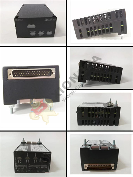
The GE RST connector DS200TBQAG1A has two 90-pin terminals and supports a maximum of 180 signal cables. Wiring terminals are marked TB1 and TB2. The GE RST terminal board DS200TBQAG1A also contains three 20-pin connectors. The GE RST terminal board DS200TBQAG1A contains five screw holes for securing the board into the board holder. Because of the junction box and multiple signal wires, the circuit board is heavy and must be securely attached to the rack. Guidelines must also be followed when removing or installing circuit boards.

DS200TBQAG1A
Terminals have been assigned ids. For all terminals connected with signal cables, write down the ids of the terminals connected to them on strips of paper or tape. Then, use a small screwdriver to loosen the screw holding the wire in the terminal. Simply loosen the screw so that you can remove the wire without removing the screw.
The board also features two 20-pin connectors that can be connected to ribbon cables. When disconnecting the ribbon cable, you can only grab the connector portion of the cable and pull it out of the circuit board. If you grab the ribbon part of the cable and pull, you may accidentally pull the wire out of the connector and lose the signal connection.
Remove the screws holding the board to the frame with one hand, then use the other hand to support the board. Grab the board from both sides with two hands and carefully remove it from the cabinet.
 中文版
中文版


