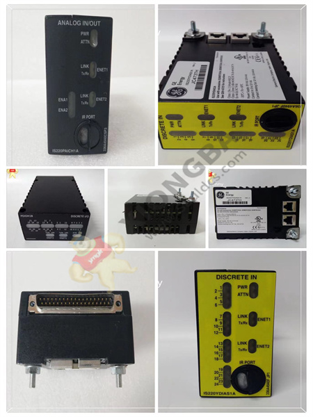
The GE RST LM6000 analog board DS200TBQEG1B has two wiring terminals. Each block contains 95 signal line terminals. The GE RST LM6000 analog board DS200TBQEG1B also contains 2 jumpers and 6 34-pin connectors. The 34-pin connector has an ID associated with it on the board surface. A set of 34-pin connectors are JQQR, JQQS, and JQQT. Another set of 34-pin connectors are the JLLR, JLLS, and JLLT. Before removing the ribbon cable from the 34-pin connector, it is a good idea to attach a label indicating where the ribbon cable is connected. This helps the installer avoid errors when replacing the cable on the board.

DS200TBQEG1B
It is also important to note how the ribbon cable is routed inside the drive. The space inside the cabinet is limited and the cabling will allow for proper airflow, which helps to cool the heating components in the cabinet. The drive is designed so that cold air enters the drive from the bottom and draws heat from the assembly as it rises. At the top of the drive, it is expelled as hot air. A second benefit of proper wiring is to keep the power cord away from signal and ribbon cables. It is well known that if the power cords are close together in the drive, they can interfere with the cables carrying the signal.
 中文版
中文版


