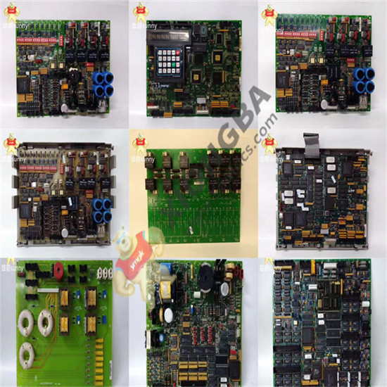
The General Electric I/O TC2000 analog board DS200TCCBG1B has an 80196 microprocessor and multiple PROM modules. It also contains an LED and 2 50-pin connectors. The LED is visible from the side view of the board. The ID of the 50-pin connector is JCC and JDD. The board is also equipped with three jumpers. The jumper has an ID printed on the surface of the circuit board.

DS200TCCBG1B
The ids are JP1, JP2, and JP3. When the original board is installed in the drive, the installer configures the board to best meet the drive’s requirements. Jumpers enable the installer to set configuration values by changing the location of the jumpers. In most cases, the default position of the jumper is used and no further action is required by the installation personnel. However, in some cases, the installer will change the position of the jumper based on the information available in the printed information supplied with the board.
 中文版
中文版


