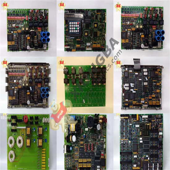
Jumper switches (J1 to J5) control the line current monitoring and generator/bus voltage monitoring functions on the DS200TCCBG3BCB board. Jumpers are also used to connect RS232 serial ports to DCOM (J14) and for testing (J15 and J16). The GE manual will provide additional information on jumper setup.

DS200TCCBG3BCB
DS200TCCBG3BCB board is a component dense board. The board contains an LED indicator light that is usually only noticeable when viewed from the side of the board. It also has multiple integrated circuits, including FPGas. The board uses resistors, a resistor network array, capacitors and diodes. Most components on the board are labeled with a reference name or original manufacturer part number to aid identification. The corners of the circuit boards have been drilled at the factory for installation in the system.
 中文版
中文版


