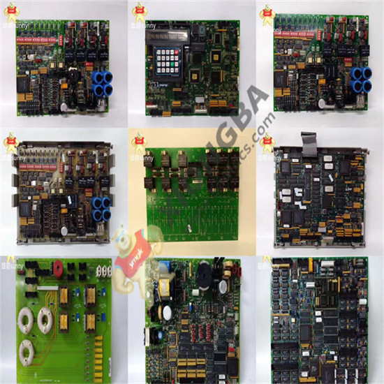
GE digital I/O board DS200TCDAG2B has a microprocessor and several programmable read-only memory (PROM) modules. It also contains 1 10-LED block and 2 50-pin connectors. The GE digital I/O board DS200TCDAG2B is also fitted with eight jumpers and one LED visible from the side of the board. The 50-pin connector on the GE digital I/O board DS200TCDAG2B transmits the signal to the DS200DTBA and DS200DTBB boards installed in the driver. The 50-pin connector is connected to a ribbon cable with one end plugged into the DS200TCDAG2B. The other end of the ribbon cable is connected to the DS200DTBA or DS200DTBB board. Before removing the plate to replace it, note how the 50-pin ribbon cable is routed inside the drive and maintain this wiring while the replacement plate is installed.
The DS200TCDAG2B is fitted with a set of 10 leds arranged in a row. When the board is energized and processed properly, the leds flash from left to right. It will continue the sequence as long as normal processing continues. If an error or warning is encountered, the LED flashes in a certain pattern to indicate the error or warning code. When the circuit board is energized, all 10 leds are lit at the same time to test the function of the LED.
When the board is mounted in a drive between several other boards in the board cabinet, the blocks of 10 leds are not visible. However, the operator can view a green LED located on the side of the board, which is designed to provide a quick visual indication of the board’s status.
 中文版
中文版


