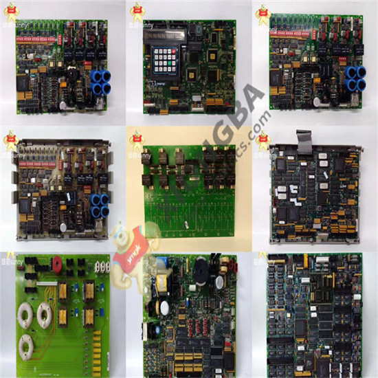
GE digital I/O board DS200TCDAG1B has a microprocessor and several programmable read-only memory (PROM) modules. It also contains 1 10-LED block and 2 50-pin connectors. The GE digital I/O board DS200TCDAG1B is also fitted with eight jumpers and one LED visible from the side of the board. The 50-pin connector carries the signals the circuit board receives from other components in the drive. Some of the signals carried by the 50-pin connector are transmitted by other boards and components to the GE digital I/O board DS200TCDAG1B. The 50-pin connector connects to the ribbon cable, which consists of 50 separate wire harnesses, each insulated from the others to provide a separate signal. Each strand consists of multiple wires that can easily snap or disconnect from the connector at the end of the banded cable. If the connection to the ribbon cable is disconnected, the signal will also be lost. You may need to run a diagnostic tool to find the missing signal.

DS200TCDAG1B
Pulling the ribbon cable to remove it from the circuit board may break the wire connections in it. Instead, use a plastic connector to disconnect it from the 50-pin connector on the circuit board. Hold the connector firmly and pull it directly out of the connector. Remove the ribbon cable without interfering with the cabling of the ribbon cable inside the driver
 中文版
中文版


