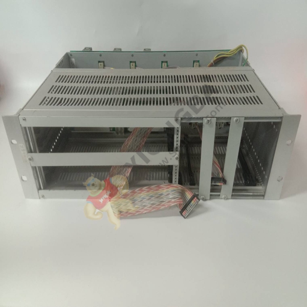
GE WES5162-9101 Loop communication interface module
(1) Arbitration bus:
Since the VME BUS can have multiple master devices, the master that gets the bus pulls the BUS BUSY LINE (BBSY) down to indicate that the bus is being applied. When BBSY is not low, the bus arbitrator will sample the bus request line BRO — BR3. Requests on BR3 have the highest priority. The daisy-chain signal BG0IN – BG3IN is used to judge who gets the control of the bus. BG0IN – BG3IN is coded to determine the priority based on the distance from the first slot. BG0OUT – BG3OUT will transmit the bus license signal generated by the first slot backward in the direction of increasing slot number. When another bus request with higher priority comes, the bus arbiter will generate a BCLR* (bus clear) signal. When the master device applying the bus detects the BCLR signal, it will know that the other master device with higher priority wants the bus, and it should quickly stop working and release the control of the bus. Since control of the bus is not gained from the slave device, the Daisy chain signal is often short-circuited to provide Daisy chain continuity.
(2) Data transfer bus:
Read and write data to the card, D00 — D31 is the actual data, the address to be accessed appears on A00 — A31, address modification code (AM0 — AM5) indicates the width of the address bus, the type of data cycle and the main device identification, address strobe AS is used to indicate that the address is valid, The master device uses the data select communication number (DS0, DS1) to control the transmission, combined with the long word select LWORD signal line to indicate the received data is valid and the length of the transmission word, the write line is used to distinguish whether the operation is read or write, DTACK (data transfer response signal) is used by the slave device to indicate the completion of the transmission, and the error in the transmission BERR indicates.
 中文版
中文版


