Abstract: Taking the centrifugal compressor of a compressor station as an example, this paper introduces the application of Siemens PLC in the compressor control system. The software, hardware and control principle of the system are explained in detail. Combined with the practical operation precautions, it is hoped to be helpful to the gas transmission industry, especially those engaged in compressor operation industry. Key word: centrifugal compressor PLC host machine SCADA ESD along with the rapid development of our country economy, the demand for energy of various industries is increasing rapidly, natural gas as a new kind of environmental protection, cheap energy is more and more popular among many users. There is a growing tension between demand and supply. Therefore, the efficient transportation of natural gas has become the main research direction and goal of scientific research departments of major production and operation units. At present, the natural gas transportation industry mainly adopts pipeline transportation, as well as gas cylinder transportation, solid transportation and other forms. In long-haul natural gas pipelines, intermediate compressor stations are generally built to increase the efficiency of gas transmission, that is, compressors are used to convert other forms of energy, such as electric energy and mechanical energy, into pressure energy, so as to increase the throughput and transmission speed per unit time. Centrifugal compressor because of its high efficiency, low maintenance, low failure rate and many characteristics, gradually stand out in all kinds of compressors, become the first choice of new compressor station. The main working parts of centrifugal compressor for gas compression are high speed rotating impeller and diffuser with increasing flow area. In short, the working principle of centrifugal compressor is to convert mechanical energy into gas pressure energy through work on the impeller and diffuser in the flow channel of the impeller and diffuser by centrifugal pressure boost and deceleration diffuser. 1. This system is mainly composed of 4 compressor units, which are driven by SIEMENS frequency control motor and MAN TURBO RV050/04 centrifugal natural gas compressor unit. The intake air source design of the unit has two kinds of air sources: medium and low pressure. 2. Control system Configuration and Description 2.1 System Hardware Structure; The system takes Siemens S7-400 series PLC as the core control component, and realizes the communication with the lower machine on the spot through optical Ethernet. The upper computer uses Siemens WINCC industrial control software, and monitors the running parameters through HMI, issues the start and stop, process adjustment and other commands. Figure 1:
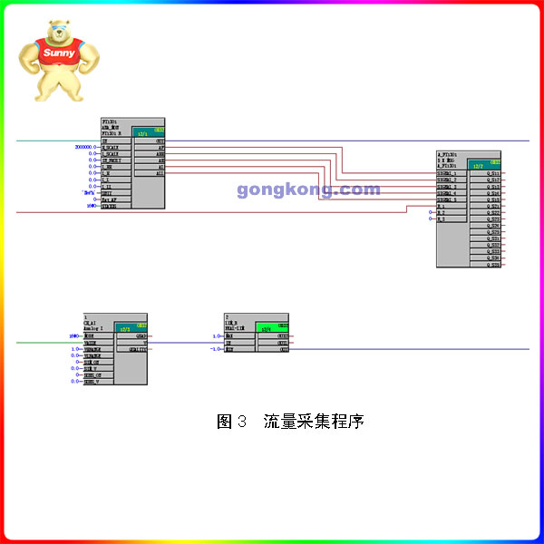
The lower computer, that is, the single unit control unit, also takes Siemens S7-400 PLC as the core control element. The distributed I/O frame ET200M field data acquisition module connected to it through the PROFIBUS private network completes data acquisition and issues control commands such as start, stop and process adjustment. The frequency converter is monitored by hard wiring. At the same time, the following relatively independent detection and control system is set up: 2.1.1 Bently vibration detection system, which can communicate with it through modbus protocol. 2.1.2 HIMA ESD system, which communicates with PROFIBUS private network. Planar 4, the fourth generation solid-state logic hardwiring system is used in the system. Through T V’s strict certification, the system has reached the highest international security level SIL4/ AK7. It is widely used to protect the safety of high risk production processes, such as high pressure polyethylene, hydrocracking, HIPPS for offshore production platforms, etc. With self-diagnosis and centralized communication function, data acquisition time is less than 4ms. 2.1.3 MCC motor control center communicates with it through PROFIBUS private network to complete the control of cooling fan and lubricating oil pump of the unit. 2.2 System software implementation; The PLC software of this system uses STEP 7 software, and the program language uses continuous function chart CFC, so that the program is clear and easy to understand. Upper computer HMI adopts industrial control software WINCC. The vibration detection system and HMIA ESD system have their own configuration software. 2.2.1 PLC lower computer software STEP 7 is a special programming configuration software for PLC products of Siemens, which has a variety of programming methods such as FDB, CFC, SFC and ladder diagram. According to the process requirements and control characteristics of compressor unit, this project uses CFC sequence function diagram for programming control. The program is mainly divided into the following parts: 2.2.1.1 Single compressor unit control program: ① Data collection; ② Valve control; (3) Start and stop sequence control; (4) oil system control; (5) anti-asthmatic control; ⑥ Third party communication; Figure 2: Data acquisition logic program
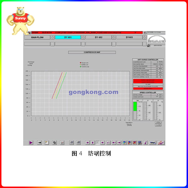
2.2.2 Host Software The host computer in this system consists of two redundant servers and a client. Hardware for the mainstream configuration of the industrial control computer, the software uses Siemens WINCC industrial control software, WINCC is Siemens and Microsoft jointly developed products, in Windows 98 or NT4.0 and based on the NT core Windows2000/ xp/2003 operating system. WinCC is an industrial technology system that solves visualization and control tasks in production process automation. It provides functional templates for industrial graphical display, information archiving and reporting. High performance process coupling, fast picture updating, and reliable data transfer make it highly practical. The HMI man-machine interface mainly consists of the following parts: 2.2.2.1 General Drawing: General drawing of the three units, including the operating state of the units, current technological process state and important operating parameters. 2.2.2.2 Single-machine General mapping: Click general mapping, including real-time operation values of each monitoring point of the unit, current working status, etc. 2.2.2.3 Anti-surge control: The anti-surge control interface of the operating unit can be used to check whether the current operating condition of the unit is stable and adjust it in time. The interface provides anti-surge control line, safety line, safety line and three critical curves, which is convenient for the operator to intuitively understand the current operating condition. Figure 4: Anti-surge control
2.2.2.4 Alarm viewing: real-time alarm and historical alarm of the unit can be viewed to facilitate unit fault analysis. 2.2.2.5 Joint control: Carry out joint operation control of 3 units, including import and export pressure control and flow control. 2.2.2.6 Logic diagram: logical sequence diagram of unit startup and shutdown, which facilitates analysis of unit startup and shutdown control and fault search. 2.2.2.7 Single control interface of valves, cooling fans and other devices. 2.2.3 Bently The configuration of the vibration monitoring system. The Bently 3500 vibration monitoring system is a relatively advanced mechanical monitoring system, which can collect data from a variety of sensors, such as speed sensor, eddy current sensor, acceleration sensor, etc. The system is designed to monitor critical equipment and provide on-site data for multiple locations and personnel for analysis. The system usually consists of field sensors, monitoring framework, software and monitoring computer. configuration software uses its special “rack configuration” software. Configuration contents include: frame template location, template parameters, alarm points, etc., which will not be repeated. The system introduced in this paper has been successfully put into operation and applied in Shaanxi – Beijing gas pipeline. The system has distinct design level, high integration and stable operation. All subsystems and data detection and collection components work stably and respond quickly. Control function perfect, very ideal to complete the gas transmission production of each link control. The system fully meets the design requirements, with convenient operation, strong reliability, complete data record, timely monitoring action and many other characteristics, at the same time greatly reduce the operation, maintenance personnel labor intensity, shorten the operation time, improve the efficiency of gas transmission.
 中文版
中文版


