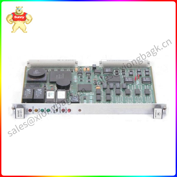
The MVME147 was tested in an FCC-compliant chassis, and meets
the requirements for Class A equipment. FCC compliance was
achieved under the following conditions:
1. Shielded cables on all external I/O ports.
2. Cable shields connected to earth ground via metal shell connectors bonded to a conductive module front panel.
3. Conductive chassis rails connected to earth ground. This provides the path for connecting shields to earth ground.
4. Front panel screws properly tightened.
For minimum RF emissions, it is essential that the conditions above be implemented; failure to do so could compromise the FCC compliance of the equipment containing the modules.
The MVME147 is a double-high VMEmodule based on the MC68030 microprocessor. It is best utilized in a 32-bit VMEbus system with both P1 and P2 backplanes. The module has high functionality with large onboard shared RAM, serial ports, and Centronics printer port. The module provides a SCSI bus controller with DMA, floating-point coprocessor, tick timer, watchdog timer, and time-of-day clock/calendar with battery backup, 4KB of static RAM with battery backup, four ROM sockets, and A32/D32 VMEbus interface with system controller functions.
The MVME147 can be operated as part of a VMEbus system with other VMEmodules such as RAM modules, CPU modules, graphics modules, and analog I/O modules. The following transition boards are compatible with the MVME147:
MVME712-12
MVME712-13
MVME712A
MVME712AM
MVME712B
MVME712M
The following equipment is required to make a complete system using the MVME147:
Terminal
Disk drives and controllers
Transition module(s) and connecting cables:
– MVME712-12
– MVME712-13
– MVME712A
– MVME712AM
– MVME712B
– MVME712M
(collectively referred to in this manual as MVME712 unless separately specified).
 中文版
中文版


