中文版
中文版

Description
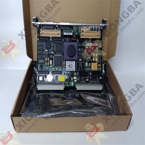
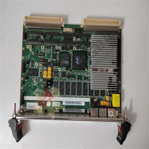
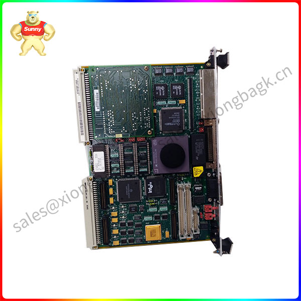
MVME162-213 MVME162 Embedded Controller
Product description
The MVME162 is based on the MC68040 or MC68LC040 microprocessor. Various versions of the MVME162 have 1 MB, 4 MB, or 8 MB of parityprotected DRAM, 8 KB of SRAM (with battery backup), time of day clock (with battery backup), Ethernet transceiver interface, two serial ports with EIA-232-D or EIA-530 interface, six tick timers, watchdog timer, a PROM socket, 1 MB Flash memory (one or four Flash devices), four IndustryPack (IP) interfaces, SCSI bus interface with DMA, VMEbus controller, and 512 KB of SRAM with battery backup.
The I/O on the MVME162 is connected to the VMEbus P2 connector. The main board is connected through a P2 transition board and cables to the transition boards. The MVME162 supports the transition boards MVME712-12,MVME712-13, MVME712M, MVME712A, MVME712AM, and MVME712B (referred to in this manual as MVME712X, unless separately specified). The MVME712X transition boards provide configuration headers and provide industry standard connectors for the I/O devices.
The I/O connection for the serial ports on the MVME162 is also provided by two DB-25 front panel I/O connectors. The MVME712 series transition boards were designed to support the MVME167 boards, but can be used on the MVME162 by following some special precautions. (Refer to the section on the Serial Communications Interface, later in this chapter, for more information.)
MVME162-213
Product parameter
❏ 25MHz 32-bit MC68040 or MC68LC040 Microprocessor
❏ 1 MB, 4 MB, or 8 MB of shared DRAM with parity protection
❏ 512 KB of SRAM with battery backup
❏ One JEDEC standard 32-pin PLCC EPROM socket (EPROMs may be shipped separately from the MVME162)
❏ One Intel 28F008SA 1M x 8 Flash memory device or four Intel 28F020 256K x 8 Flash memory devices (1 MB Flash memory total)
❏ 8K by 8 Non-Volatile RAM and time of day clock with battery backup
❏ Four 32-bit Tick Timers (in the MCchip ASIC) for periodic interrupts
❏ Two 32-bit Tick Timers (in the VMEchip2 ASIC) for periodic interrupts
❏ Watchdog timer
❏ Eight software interrupts (for MVME162 versions that have the VMEchip2)
❏ I/O– Two serial ports (one EIA-232-D DCE; one EIA-232-D or EIA-530
DCE/DTE)
– Serial port controller (Zilog Z85230)
– Optional Small Computer Systems Interface (SCSI) bus interface with 32-bit local bus burst Direct Memory Access (DMA) (NCR 53C710 controller)
– Optional LAN Ethernet transceiver interface with 32-bit local bus DMA (Intel 82596CA controller)
– Four MVIP IndustryPack interfaces
❏ VMEbus interface
– VMEbus system controller functions
Application field
These transition boards provide configuration headers, serial port drivers and industry standard connectors for the I/O devices
The VMEbus interface is provided by an ASIC called the VMEchip2. The VMEchip2 includes two tick timers, a watchdog timer, programmable map decoders for the master and slave interfaces, and a VMEbus to/from local bus DMA controller, a VMEbus to/from local bus non-DMA programmed access interface, a VMEbus interrupter, a VMEbus system controller, a VMEbus interrupt handler, and a VMEbus requester.
Processor-to-VMEbus transfers can be D8, D16, or D32. VMEchip2 DMA transfers to the VMEbus, however, can be D16, D32, D16/BLT, D32/BLT, or D64/MBLT.
The MCchip ASIC provides four tick timers, the interface to the LAN chip, SCSI chip, serial port chip, BBRAM, and the programmable interface for the parity-protected DRAM and/or SRAM mezzanine board.
The IndustryPack Interface Controller (IPIC) ASIC provides control and status information for up to four single size IndustryPacks (IPs) or up to two double size IPs that can be plugged into the MVME162 main module.
Please contact Sunny sales@xiongbagk.cn for the best price.
➱ sales manager: Sunny
➱ email mailto: sales@xiongbagk.cn
➱ Skype/WeChat: 18059884797
➱ phone/Whatsapp: + 86 18059884797
➱ QQ: 3095989363
➱ Website:www.sauldcs.com